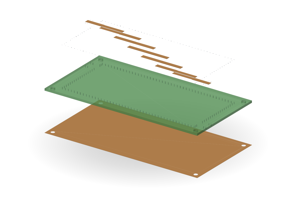
PCB band-pass filters
Coupled-line and hairpin band-pass filters on FR-4 or RO4003C
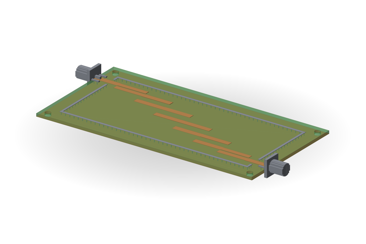
Overview
Chebyshev or Butterworth; coupled-line or hairpin; FR-4 or RO4003C; shield, via fence, SMA.
From the simplest to the most complex: coupled lines on FR-4, up to a hairpin topology on RO4003C with a shield, via fence and SMA connectors.
Typical performance
- VSWR < 1.5 over the passbandtypical
- Fractional bandwidth ≈ 5–25 %typical
- Passband loss ≈ 1–3 dB on FR-4, ≈ 0.5–1.5 dB on RO4003Ctypical
Typical values describe the antenna class, not a guarantee for a unit; “computed” marks our own simulated example.
View A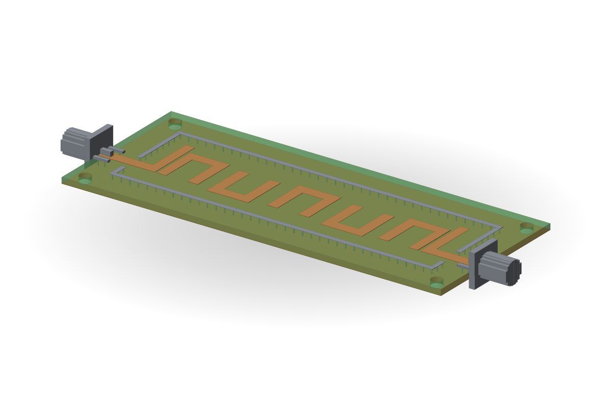
Hairpin topology
What we optimise
| Pos. | Parameter |
|---|---|
| P1 | Centre frequency |
| P2 | Bandwidth |
| P3 | Ripple |
What you receive
| Pos. | Deliverable |
|---|---|
| D1 | Board and shield manufacturing files |
| D2 | A 3D model |
| D3 | S-parameters |
| D4 | A measurement protocol |
Designs