RF and antenna engineering shaped by your requirements
Define the performance objectives, operating conditions and physical constraints that guide your next antenna or RF design.
Discuss your RF requirements Antenna families
RF & antenna engineering · Application envelope
From your specification to a manufacturing-ready design. Manufacturing and unit measurement on request.
Space
Satellite links and the ground terminals that talk to them.
Air
Antennas carried by aircraft and unmanned platforms, linked through the atmosphere.
Ground
Fixed sites and mobile installations in land radio networks.
Marine
Shipborne and coastal links, built for the marine environment.
Scope agreed per specification
Antenna types
Every design is a parametric 3D model: the sizes of all parts are linked and optimised together for your band, VSWR and size. From the simplest to the most complex in every family.
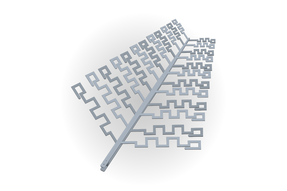 01LPDA: log-periodic dipole arraysWideband directional antennas for EMC pre-compliance, SDR, radio monitoring, ham radio and FPV drones.
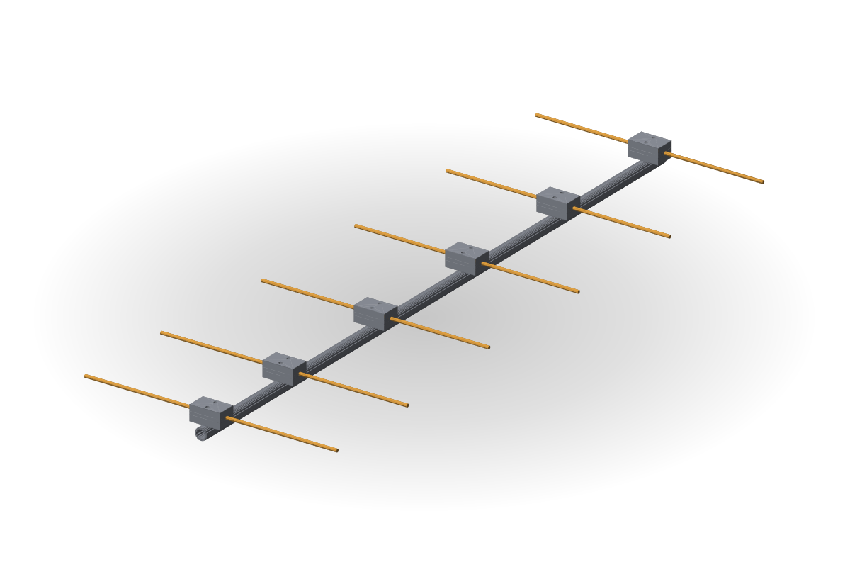 02Yagi-Uda and MoxonDirectional high-gain antennas for ham radio, satellite links, LoRa and FPV.
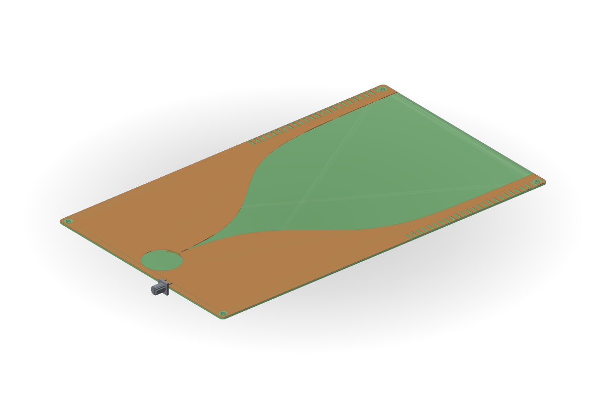 03Vivaldi antennasUltra-wideband tapered-slot antennas for R&D, UWB links, ground-penetrating radar, SDR, measurements and EMC testing.
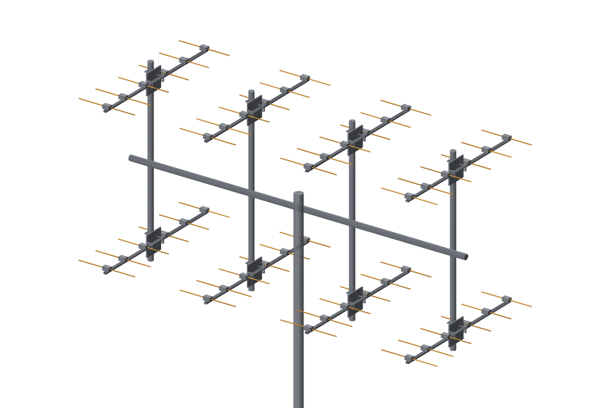 04Antenna arraysArrays of Yagis, dipoles or LPDAs for higher gain and a narrower beam: H-frame, mast, clamps, Wilkinson divider.
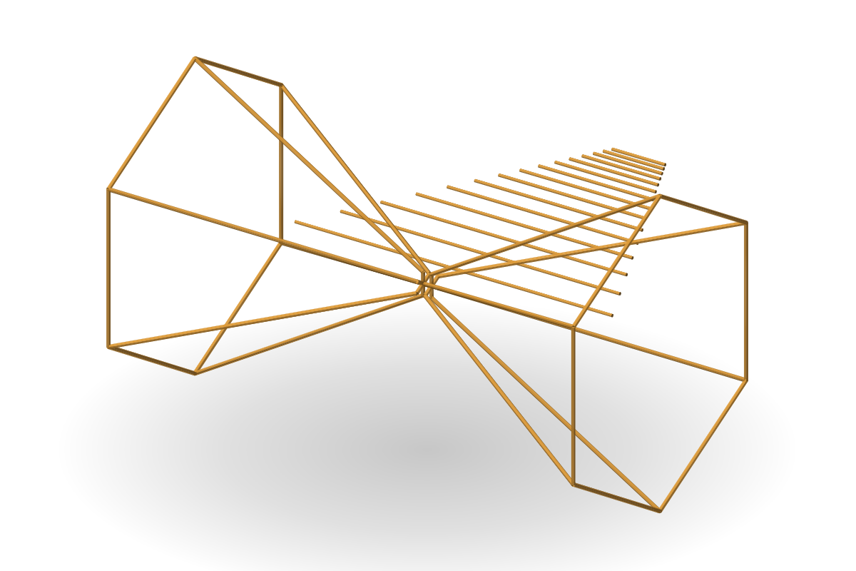 05Bicone, discone, bicone-logWideband antennas for EMC testing and radio monitoring: rod bicones, discones and bicone-log antennas with a balun and matching network.
 06Helical and spiral antennasCircularly polarised antennas for satellite navigation, links and direction finding: helices, quadrifilar, flat and conical spirals, printed spirals.
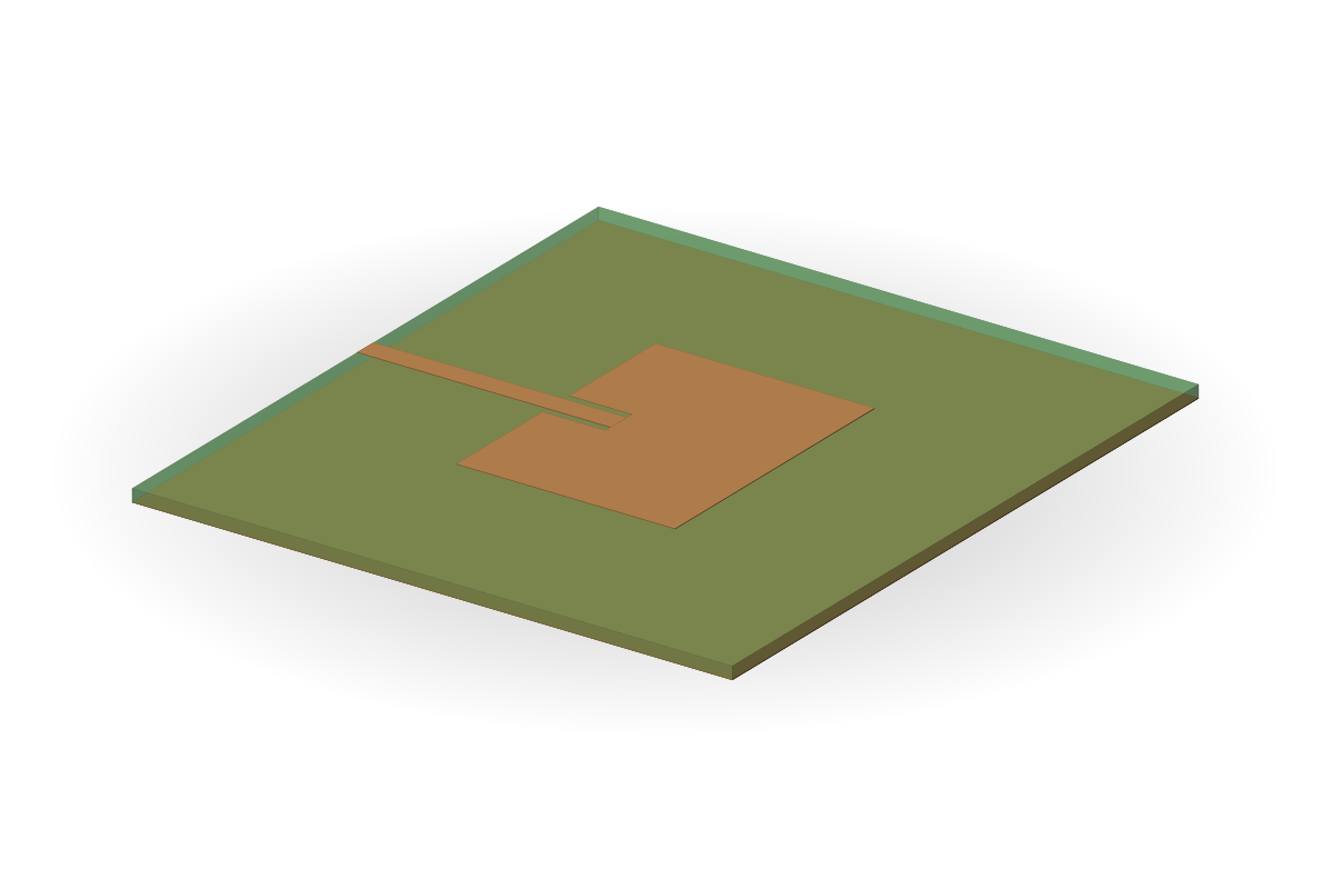 07Patch antennas and sector panelsFlat antennas for Wi-Fi, ISM, GNSS and links: linear or circular polarisation, inset or probe feed, sector panels of several patches.
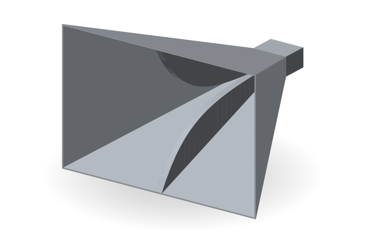 08Double-ridged horns, 1–18 GHzMeasurement horns for EMC testing, calibration and antenna measurements: smooth ridge profiles, a coaxial transition, solid or open side walls.
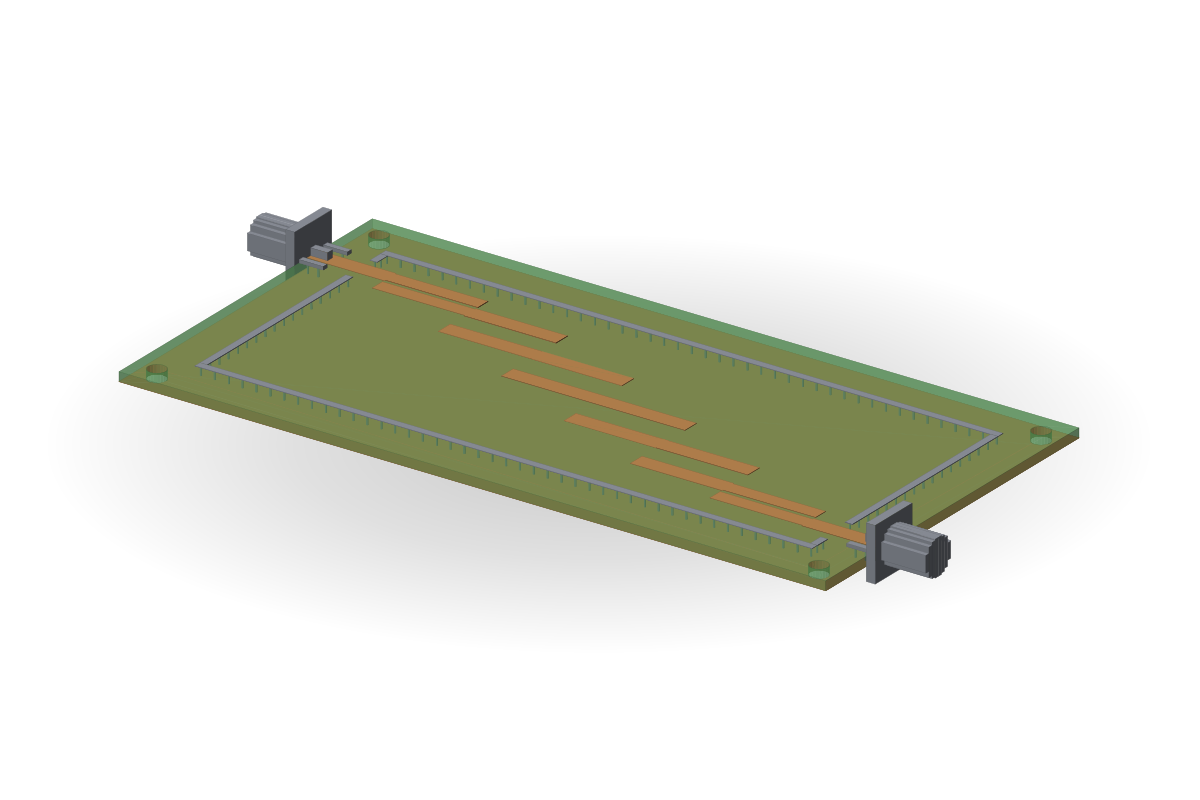 09PCB band-pass filtersChebyshev or Butterworth band-pass filters on a board: coupled-line or hairpin, FR-4 or RO4003C, shield, via fence, SMA.
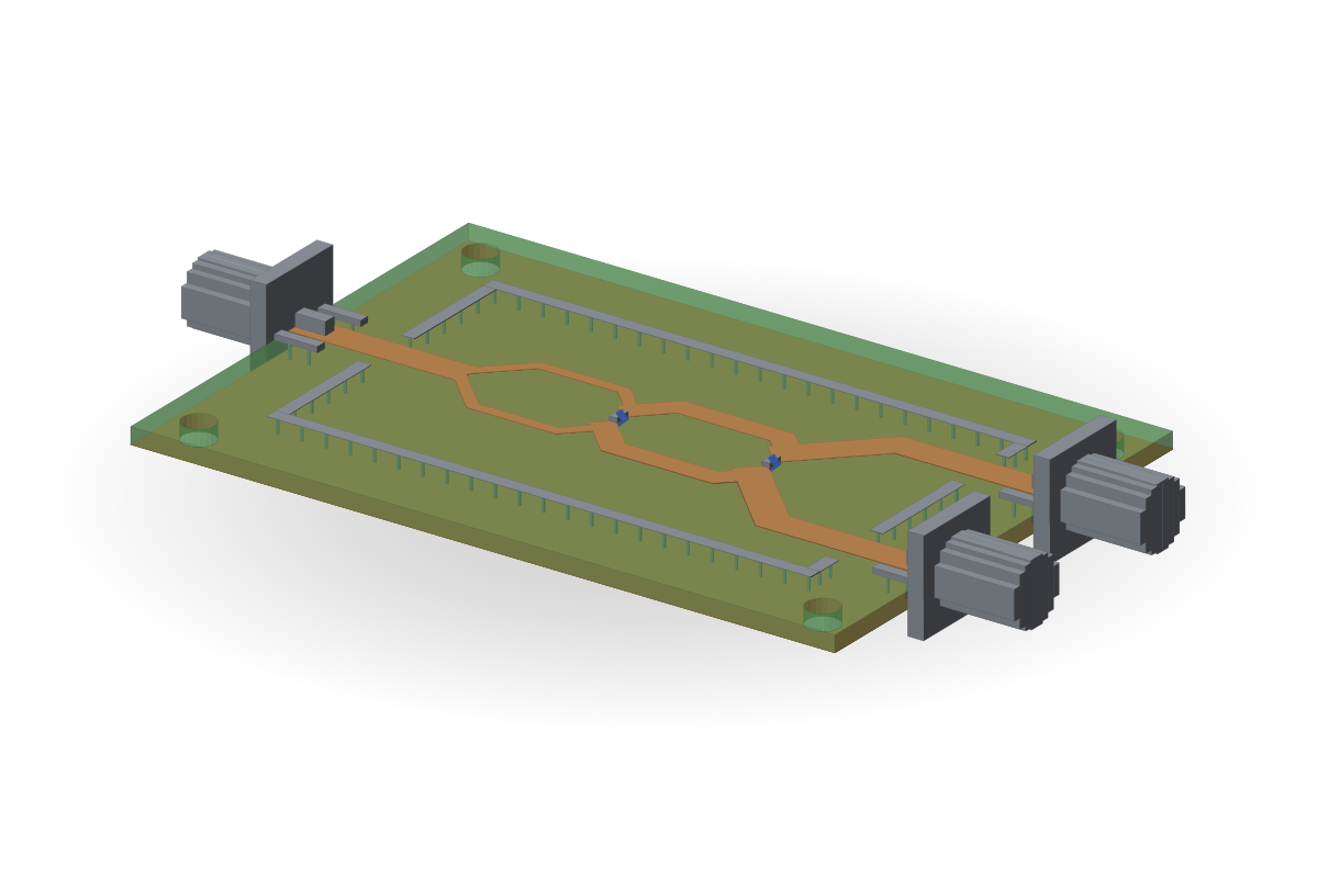 10Wilkinson dividersEqual or unequal power split, 1–4 sections, resistors on the board; shield and SMA connectors.
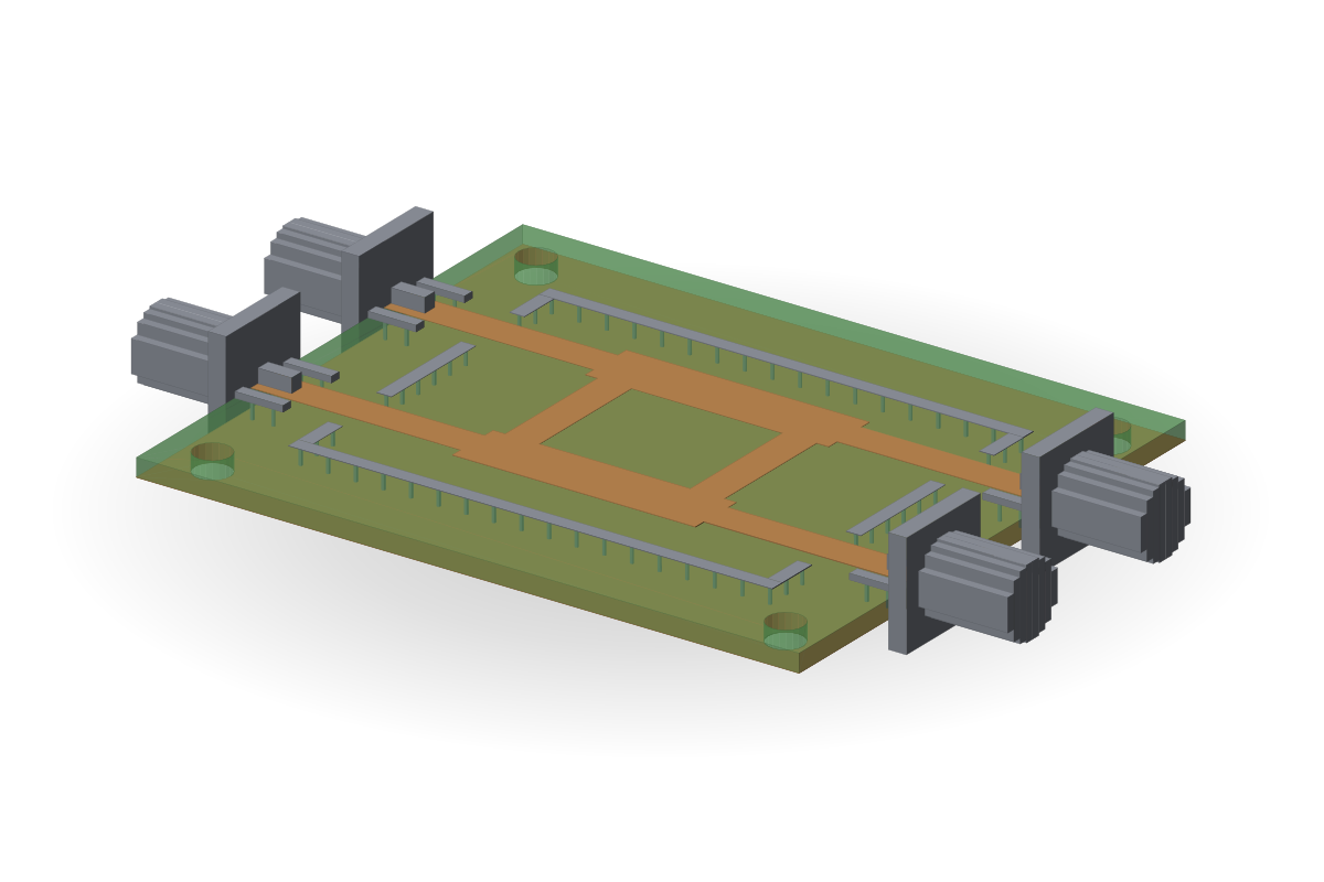 11Hybrids and directional couplersFour-port board components: a power split with a 90° or 180° phase shift and couplers with a set coupling, for arrays, balanced amplifiers and measurements.
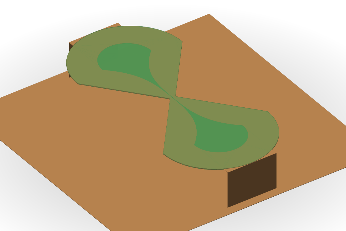 12Batwing and corner antennasA 200–400 MHz sheet-metal batwing over a ground plane, a corrugated or meander batwing, and a corner antenna with circular polarisation.
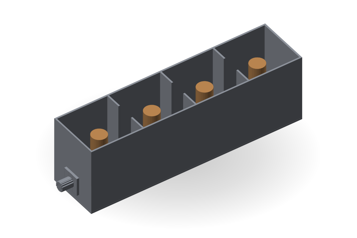 13Resonator filters and duplexersFrom a 3-resonator filter to a duplexer of two 4-resonator channels; coupling-matrix design, the mechanical build on request.
Typical values describe the antenna class, not a guarantee for a unit; “computed” marks our own simulated example.
Scope of the work
Start with the specification
A useful engineering brief connects the intended application to the requirements that can be evaluated. Frequency range, bandwidth, gain, radiation behavior, polarization, impedance and installation constraints all influence the work.
We begin by clarifying the target requirements and agreeing what will be delivered and how it will be assessed.
Antenna design and refinement
Discuss new antenna requirements or the need to improve an existing design. The engagement establishes which characteristics matter most and which mechanical, interface or manufacturing constraints must be preserved.
RF requirements and feasibility
Review the technical objectives and tradeoffs before committing to a design scope. Identify missing inputs, conflicting requirements and the verification work needed to support a meaningful decision.
Integration considerations
Consider the intended installation, surrounding structure, interfaces and operating conditions as part of the brief. Agree which integration factors belong within the design engagement and which require separate validation.
Defined engineering deliverables
The proposal specifies the design outputs and documentation included in the work. Depending on scope, these may include agreed geometry, drawings, models, specifications and supporting evaluation material.
Manufacturing, prototyping and physical measurements are defined separately when applicable.
Clear evidence of performance
Calculated, simulated and measured results answer different questions. Any performance material supplied or published identifies the basis of the result and the conditions under which it was obtained.
How we work
From your specification to a manufacturing-ready design. Manufacturing and unit measurement on request.
- Specificationband, VSWR, gain, size, connector
- Synthesisstarting geometry
- Optimisationmethod of moments, FDTD, cluster; full-wave cross-check
- TolerancesLPDA, Vivaldi, filters; others on request
- Manufacturing packagemanufacturing files, drawings, bill of materials
- Measurement & protocolS11 of every unit, serial numberon request
How an engagement proceeds
- Review the application and technical requirements.
- Agree the scope, constraints and acceptance criteria.
- Perform the scoped engineering work.
- Review the outputs against the agreed criteria.
- Deliver the specified design material and documentation.
Frequently asked questions
What should we provide for an initial discussion?
Share the intended application, target characteristics, physical constraints and any existing design material you can disclose.
Can you work from an existing design?
Existing geometry, specifications and evaluation results can inform the scope of a refinement engagement.
Are prototypes and measurements included?
Their inclusion depends on the agreed scope. The proposal identifies responsibility for each activity.