Circularly polarised antennas: axial-mode helices, quadrifilar, flat and conical spirals
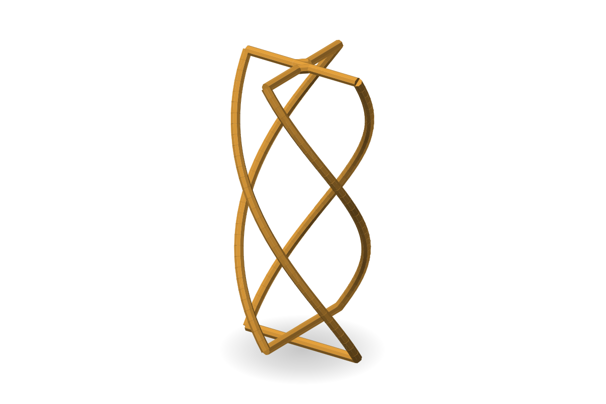
Quadrifilar (QFH), GNSS L1
Overview
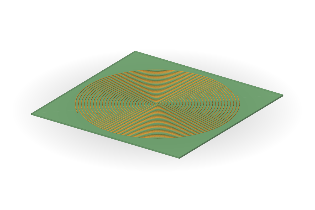
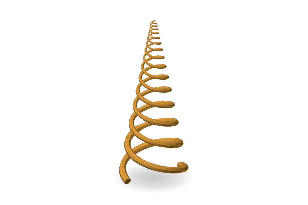
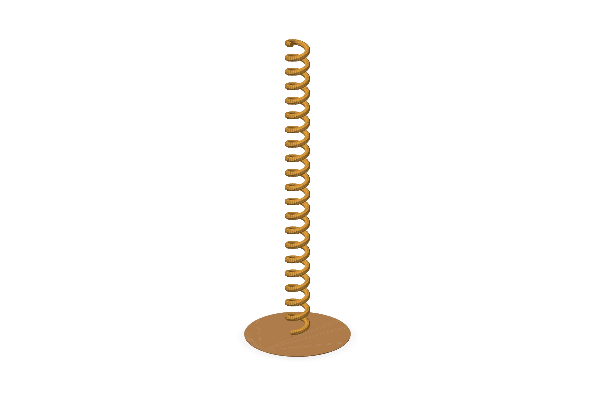
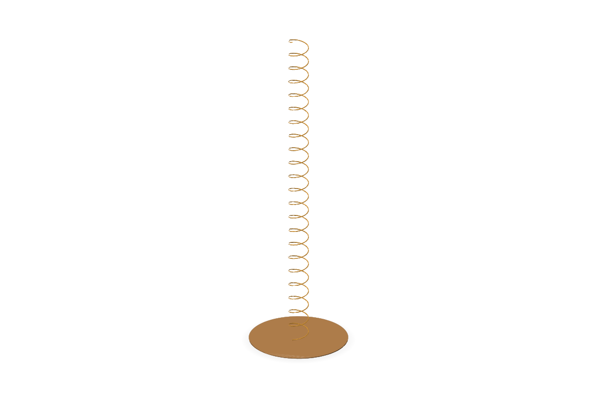
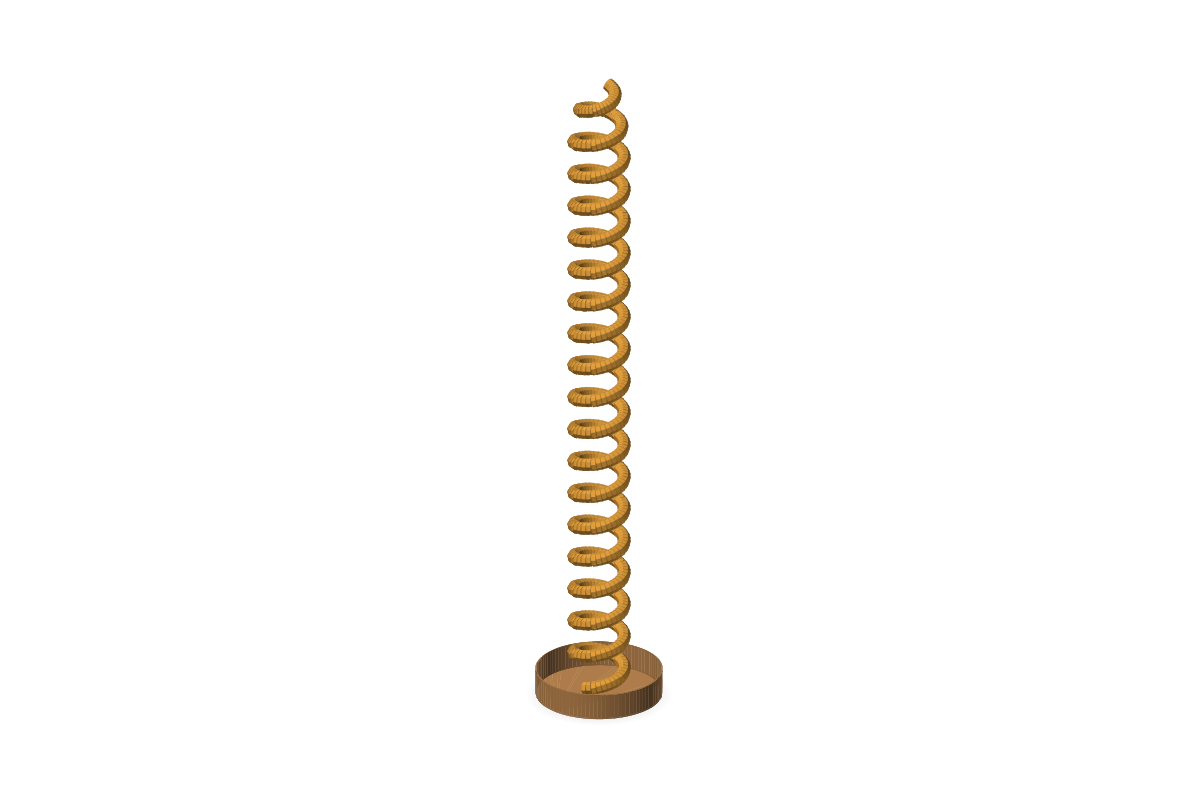
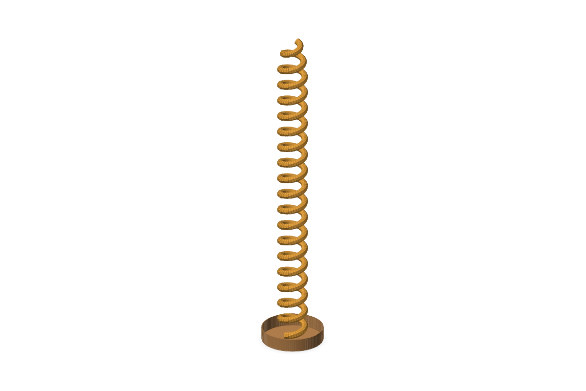
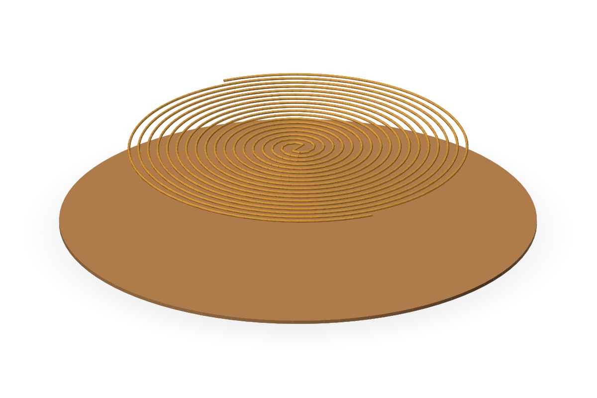
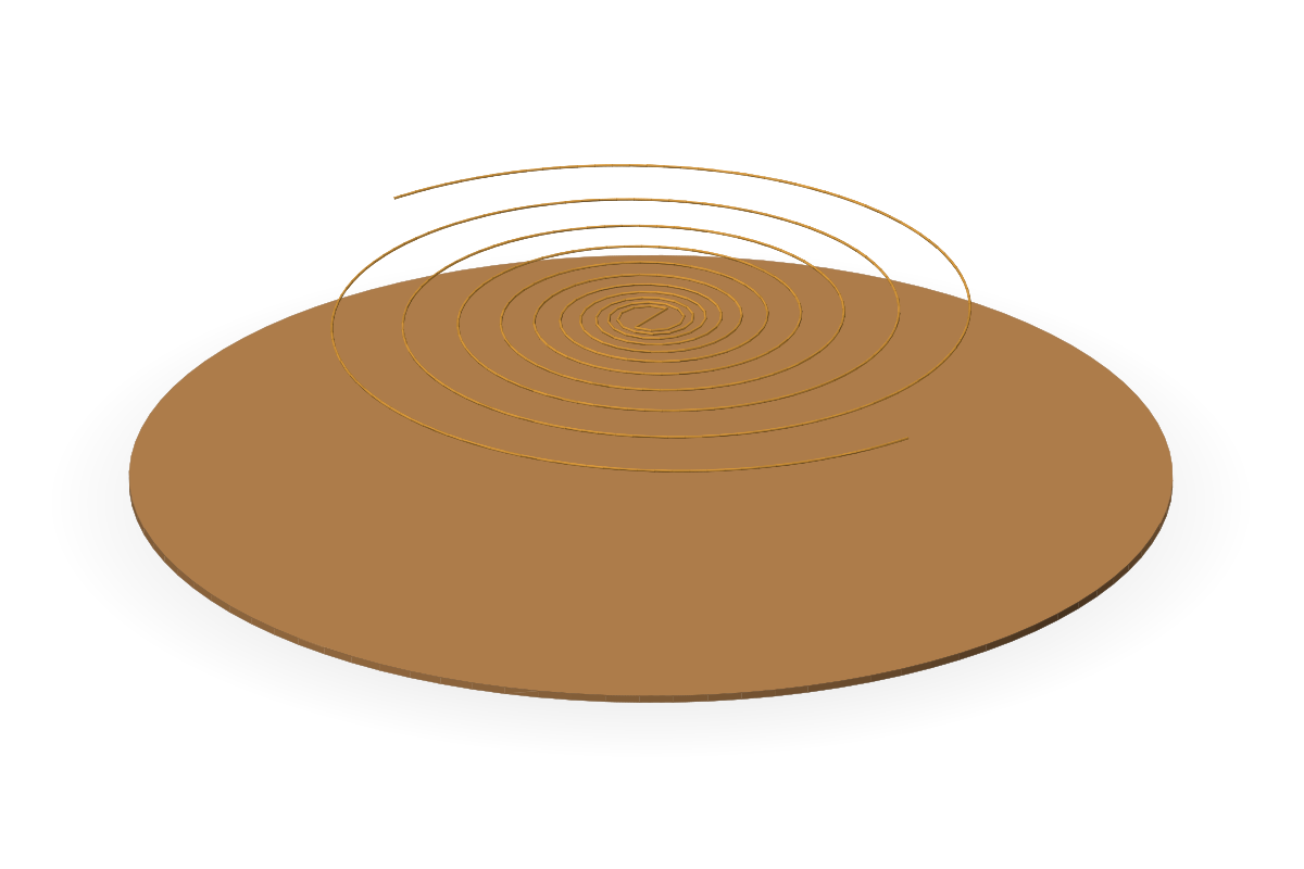
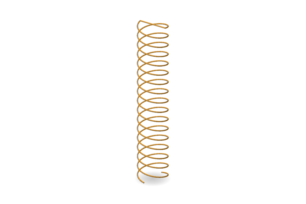
Circularly polarised antennas for satellite navigation, links and direction finding: an axial-mode ribbon or wire helix, quadrifilar, flat Archimedean and equiangular spirals, a conical log-spiral, a backfire bifilar, a printed spiral on a board.
From the simplest to the most complex: an axial-mode ribbon or wire helix for GNSS L1, up to a printed 2–18 GHz spiral on RO4003C, a conical log-spiral, quadrifilar and backfire bifilar designs.
Typical performance
Axial-mode helix: gain ≈ 8–15 dBi, band ≈ 1.7 : 1, beamwidth ≈ 30–50°typical
Flat spirals and the conical log-spiral: band ≈ 10 : 1 or wider, gain ≈ 3–9 dBi, beamwidth ≈ 60–90°typical
QFH: hemispherical pattern, beamwidth ≈ 100–130°, gain ≈ 2–5 dBitypical
Axial ratio < 3 dB on axis over the band; circular polarisation, either sensetypical
Typical values describe the antenna class, not a guarantee for a unit; “computed” marks our own simulated example.
Printed Archimedean spiral, 2–18 GHz, RO4003CConical log-spiral, 1–3 GHzAxial-mode ribbon helix, GNSS L1Axial-mode wire helix, GNSS L1Helix with a cup reflector and a tapered endHelix with a cup reflector and a matching stripArchimedean spiral over a reflector, 1–4 GHzEquiangular spiral over a reflector, 1–4 GHzBackfire bifilar helix, GNSS L1