LPDA: log-periodic dipole arrays
Wideband directional antennas, from straight plates to hairpin and meander arms
Overview
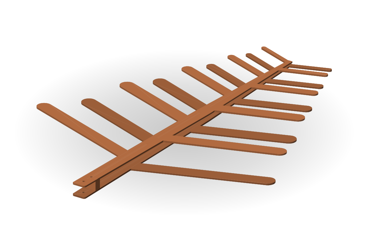
Wideband directional antennas for EMC pre-compliance testing, software-defined radio (SDR), radio monitoring, ham radio and FPV drones. A parametric model with up to 27 parameters optimised together, plus per-dipole corrections: from straight arms to a hairpin with a meander on both branches. The tail always ends in a short; on metal it is a block with a boom extension that also mounts the antenna.
Values given for a design below come from our own simulations (computed examples); they are not measured guarantees.
Typical performance
- VSWR < 2 over 195–410 MHz (hairpin arms with tilt, 12 dipoles, pictured under the variants)computed
- Band 2 : 1 … 10 : 1 by the dipole count, 8–24 dipolestypical
- Directivity ≈ 7–11 dBtypical
- Hairpin: span ≈ 0.57 m against ≈ 0.75 m with straight arms at 195 MHztypical
- Linear polarisationtypical
Typical values describe the antenna class, not a guarantee for a unit; “computed” marks our own simulated example.
Arm shapes
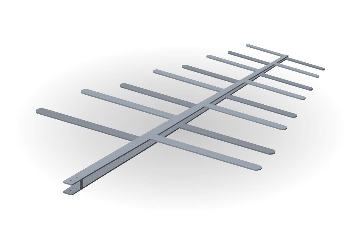
Straight arms
The simplest design and the most tolerant to manufacturing spread: two plates, laser cut, no bending. The widest band per dipole.
- Computed example: VSWR < 2 over 300–800 MHz; 8 dipoles, span ≈ 0.48 m, 2 mm aluminium.
- Use: EMC pre-compliance, test ranges, radio monitoring.
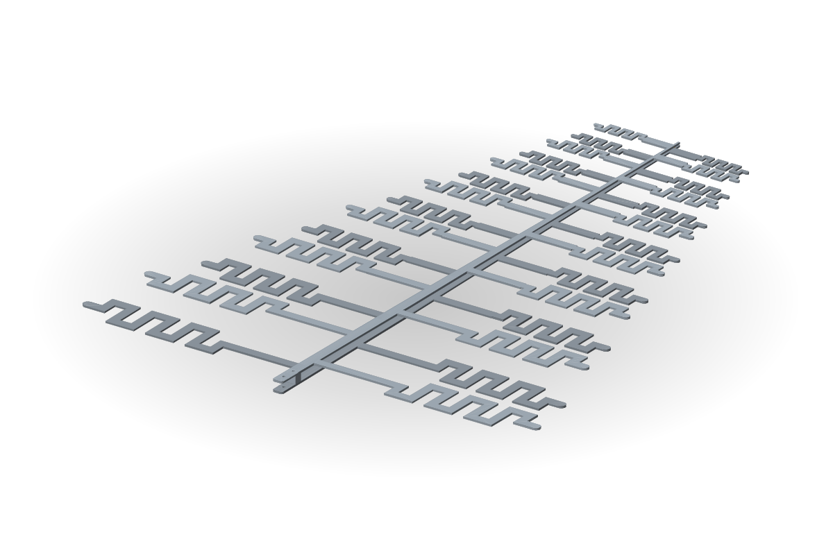
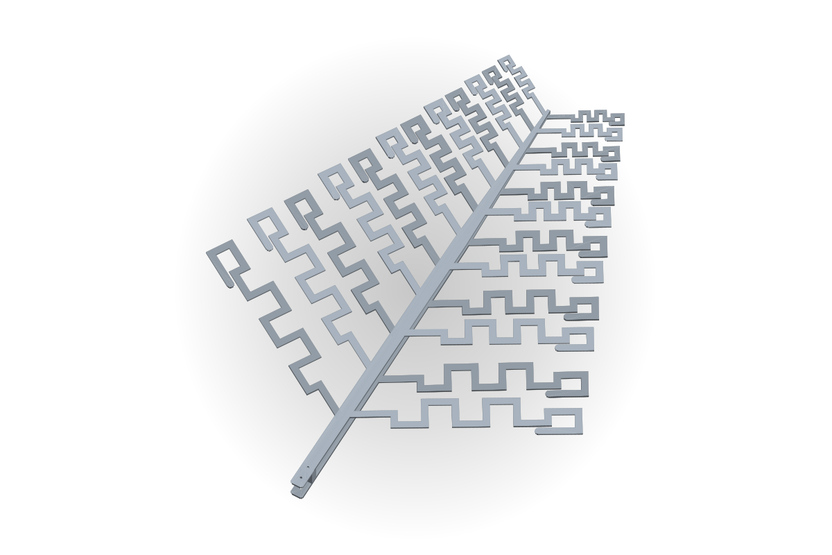
Meander arms
The arm is folded into a zigzag: the same lowest frequency with a smaller span. Meander height and section count scale with every dipole.
- Computed example: VSWR < 2 over 195–400 MHz; 14 dipoles, 7 meander sections, span ≈ 0.6 m (straight: ≈ 0.75 m).
- Use: lower VHF and UHF where the span is limited by the mast, the room or the drone.
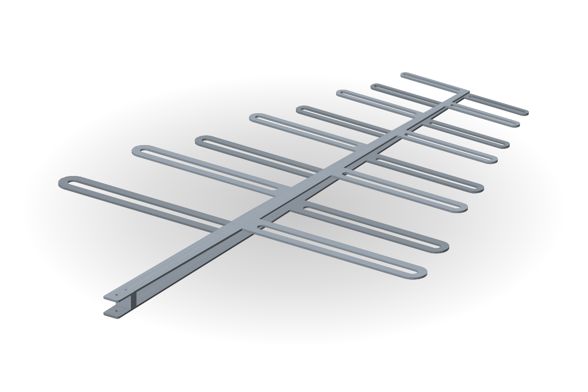
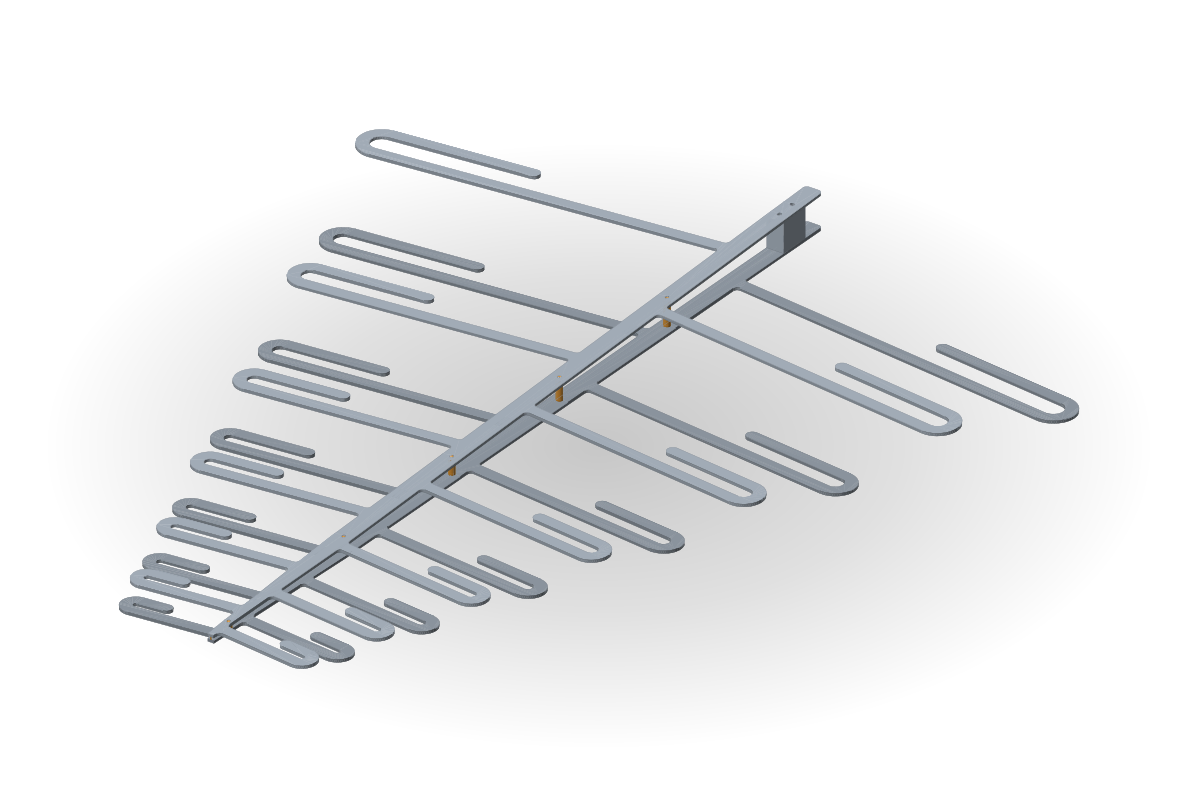
Folded loop arms
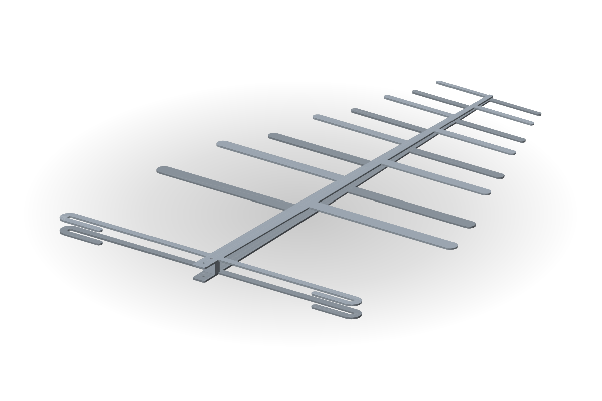
Two parallel traces with a slot, joined at the tip: a stiffer arm, a lower dipole Q, a smoother input impedance over the band.
- Computed example: VSWR < 2 over 300–800 MHz; 8 dipoles, slot 5 % of the arm length, 2 mm aluminium.
- Use: fixed and vehicle antennas under wind and vibration, test ranges.
Hats, tilt, reflector
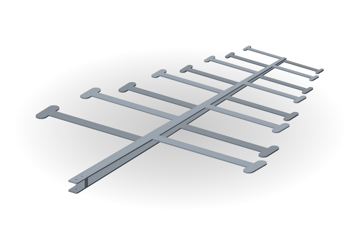
T-hat end loading
A cross bar at the arm tip adds capacitance: the dipole resonance drops by 10–15 % for the same span, without bending or a meander.
- Computed example: VSWR < 2 over 300–800 MHz; 8 dipoles, hat 25 % of the arm length.
- Use: compact SDR and monitoring antennas keeping the same lowest frequency.
Tilted arms (V shape)
The arms lean towards the apex: a narrower antenna for the same arm length and a narrower pattern in the dipole plane. The tilt can vary from the largest dipole to the smallest.
- Computed example: VSWR < 2 over 350–750 MHz; 9 dipoles, 20° tilt, 2 mm copper.
- Use: direction finding and monitoring, drone and mast antennas with a width limit.
Tail reflector
A parasitic, electrically longer dipole behind the largest one, within the tail: the same boom length, less back radiation at the lower band edge.
- Computed example: VSWR < 2 over 300–800 MHz; 8 dipoles and a hairpin reflector, the boom length unchanged.
- Use: indoor and range measurements where reflections from behind interfere.
LPDA on printed boards
Double-sided board with meander
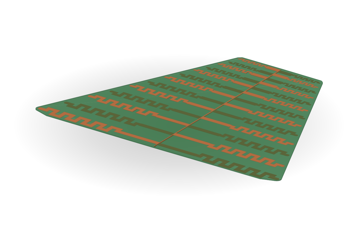
Arms A and B in copper on both sides of one FR-4 board: light, repeatable in series, no mechanical assembly.
- Computed example: VSWR < 2 over 195–400 MHz; 13 dipoles, 10 meander sections, 1.5 mm FR-4.
- Use: SDR, receiving antennas, series products for integrators.
Two boards at an angle
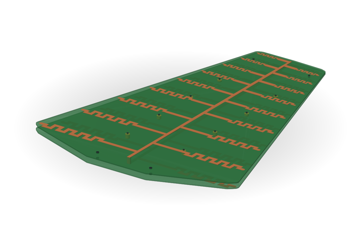
Two identical single-sided boards, the second one flipped; screws through dielectric inserts hold the gap and the angle. The feed line works as in a metal LPDA.
- Computed example: VSWR < 2 over 340–800 MHz; 17 dipoles, 9 meander sections, 1.6 mm FR-4, 3D-printed inserts.
- Use: measurement and monitoring antennas with a wider band than a single board.
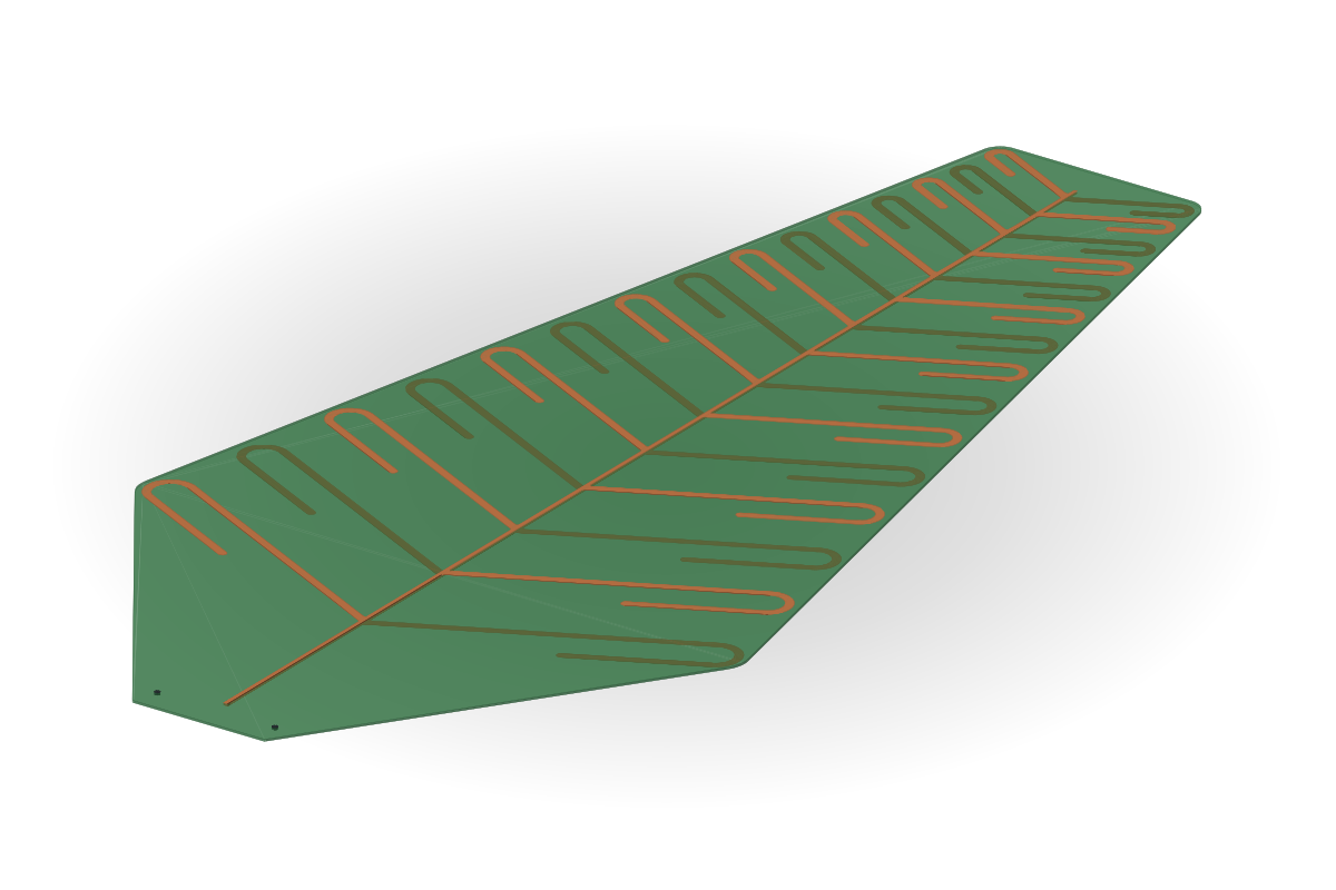
Board with hairpin arms
Hairpin arms with a 26° tilt and rounded joints to the boom: the smallest board span for a 195 MHz lowest frequency.
- Computed example: VSWR < 2 over 195–410 MHz; 15 dipoles, 1.6 mm FR-4, 1.5 mm fillets.
- Use: compact FPV and SDR antennas at low frequencies.
What we optimise
| Pos. | Parameter |
|---|---|
| P1 | τ, σ, number, length and width of dipoles |
| P2 | Arm shape and tilt |
| P3 | Feed line, tail, reflector |
What you receive
| Pos. | Deliverable |
|---|---|
| D1 | Files for laser cutting or board manufacture |
| D2 | Drawings of the short block and spacers |
| D3 | A 3D model |
| D4 | A measurement protocol of S11 and antenna factor |
Designs